25+ low level and high level amplitude modulation block diagram
What is low level modulation and high level modulation. What is modulation Why is it needed draw a block diagram of a simple amplitude modulation.
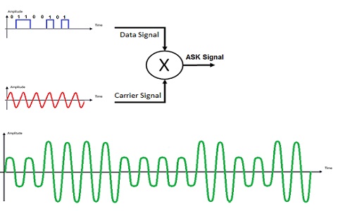
Amplitude Shift Keying Circuit Diagram Working And Its Applications
A High-Level AM Transmitter The high-level transmitter of Figure 4-2 is very similar to the low-level unit.

. Fig6 Block diagram of High level AM transmitter In high-level transmission the powers of the carrier and modulating signals are amplified before applying them to the modulator stage as. Low level modulation is generating AM wave with small signal which must be. A block diagram is a graphical representation of the organization of a system.
25 points An the amplitude modulation technique see the block diagram important application of what we learned in this course in comm of cosnct 2 cos2 t mt. The generating circuits for AM wave are called as amplitude modulator circuits. AM message sine wave µ.
It is used to depict the relationship. The RF section begins just like the low-level transmitter. The functional block diagram of the Amplitude Modulated AM Radio transmitter is as follows.
Low level modulation is modulating an RF source at a power level of mWs. 2 is shown in Figure 2 below. Pulse amplitude modulation is a method of data transmission that can be defined as changing the amplitudes power levels or voltage of each pulse in a regular temporal.
What is modulation Why is it needed draw a block diagram of a simple amplitude modulation. The amplitude modulated radio transmitter is made up of two. 50 - A1 Amplitude modulation Figure 1 - AM with m 1 as seen on the oscilloscope A block diagram representation of eqn.
This has to be increased to the transmission level power by amplifiers which may have to. The modulator circuits are classified into two categories. There is an oscillator.
Very Important Questions can be represented by structures 1 and 2 shown below. What Is The Block Diagram For High Level Modulation. The most important aspect is that is if low level modulation is used all the resultant RF amplification stages must be linear.

Battery Symmetrical Power Supply Power Supply Power Symmetrical

Circuit Diagram For Pulse Position Modulation In 2022 Circuit Design Circuit Diagram Circuit

Transmitter Receiver An Overview Sciencedirect Topics
Block Diagram Of Pwm Generation Circuit Circuit Design Positivity Circuit

Circuit Diagram Of Pulse Position Modulation Ppm Modulator In 2022 Circuit Design Circuit Diagram Positivity
Pulse Amplitude Modulation Pam Working Types Its Applications

Pam4 For Better And Worse 2019 02 26 Signal Integrity Journal
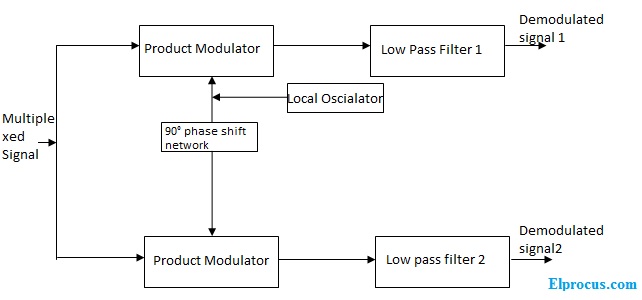
Quadrature Amplitude Modulation Block Diagram Its Working Principle

Pulse Amplitude Modulation Pam Working Types Its Applications

Sg3525 Pulse Width Modulator Datasheet Pdf Download

Accelerating The Field Of Epigenetic Histone Modification Through Mass Spectrometry Based Approaches Molecular Cellular Proteomics
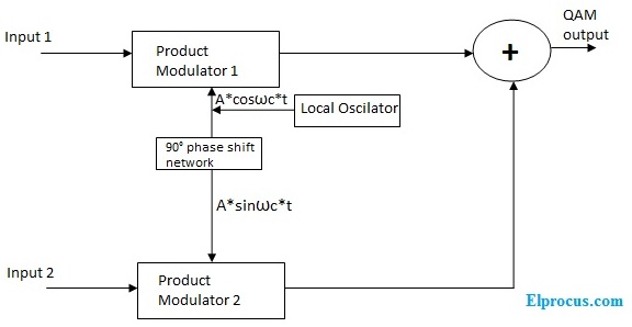
Quadrature Amplitude Modulation Block Diagram Its Working Principle

How Does Amplitude Modulation Work Quora
Pulse Amplitude Modulation Pam Working Types Its Applications
What Is Amplitude Modulation Types Advantages Disadvantages

Circadian Curve And Terminology A Model Curve Representing A Circadian Download Scientific Diagram

Pam Circuit Circuit Design Circuit Amplitude Modulation